1. Shell-Reinforced SPA Fabrication
The technique used to fabricate the soft pneumatic actuators presented ensures robustness and repeatability in manufacturing, since it leaves minimal manual intervention and margin for error.
The actuators are composed of two main parts: 1) the actuator body and 2) the un-stretchable shell. The actuator body is made out of highly elastomeric siloxane material (EcoflexTM 00-30, Smooth-on-Inc., PA, USA). The un-stretchable shell is made from a much stiffer plastic material (polyethylene terephthalate (PET), Q-ConnectTM). Images of two types of fabricated actuators, in bending and linear motion are shown below.
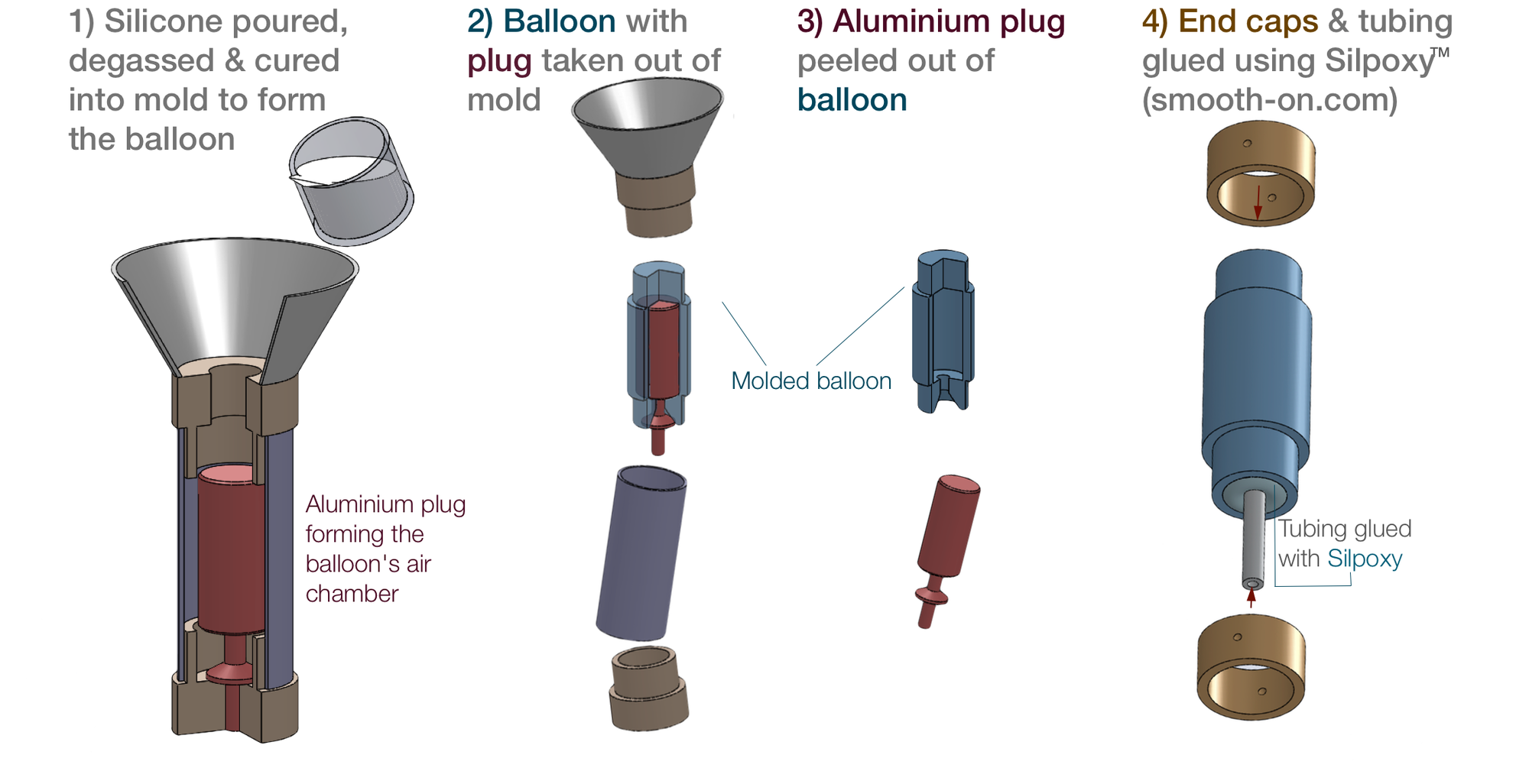
1. FABRICATING ACTUATOR BODY
- SINGLE STEP MOLDING: The actuator comprises of a single air chamber, created in a single-step molding process. This is done to avoid the traditionally used two-step molding process for creating soft pneumatic actuators in which two separate halves need to be glued to form the air chambers, thereby reducing fabrication errors and possibility of delamination at the interface.
- GRIPPING AT CHAMBER ENDS: At each end of the chamber, an additional length of rubber material is provided to facilitate attachment of fixtures for gripping the actuator during testing, since gripping on the active chamber portion can potentially constrict the air flow passage and alter the performance of the actuator.
- END CAPS: To grip the actuator for testing, end-caps are attached at the actuator at the border of its air chamber, thus ensuring maximum force/torque delivery.
2. FABRICATING UN-STRETCHABLE SHELL
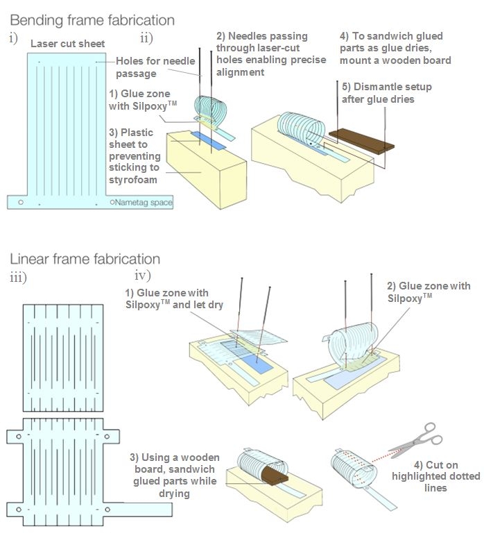
- SHELL PATTERN: The un-stretchable shell mounted on top of the actuator body surface constrains the actuator body to inflate in only the desired configuration. The pattern created on the shell surface governs the displacement obtained. Bending and linear actuators were fabricated using the sequence shown below.
- LASER CUTTING: To construct the shells, 2D patterns are cut out of universal inkjet transparency films made from PET (Q-ConnectTM) using a laser cutter. Multiple slits are cut out on the shell surface in well-defined patterns. These slits permit the appropriate level of inflation of the contained rubbery material in the desired direction while the remaining uncut portion provides circumferential reinforcement to avoid excessive radial expansion of the actuator body.
- ROLLING UP SHELLS AND GLUING: The cut patterns are then rolled up and glued into a cylindrical shape, to conform to the shape of the encased actuator body. Unlike the shell for bending actuators, which requires only one laser-cut pattern per shell, the shell for linear actuators consists of a glued assembly of two symmetric patterns (see Figure below). For these actuators, having two symmetrically layered glue-zone bands ensures the expansion of the actuator in the linear motion desired.
- ATTACHING SHELL TO BODY: To prevent the shell from slipping out over the actuator body at high pressures, the shell and the body are maintained in place by screws drilled through the end caps and the actuator wall thickness. To track the position of the actuator with a high speed camera, tracking points are also glued onto each end-cap.
3. INFLATION COMPENSATION AT CHAMBER ENDS
From experimental testing, it was observed that at the border of the air chambers, the ballooning rate is approximately double than that at other portions along the the rest of the laces. This is due to the fact that the air flow at the edge of the chamber undergoes a dramatic change in cross-sectional area from a very small inlet diameter to a much larger diameter for the air chamber, thereby introducing vortices and turbulent flow in that region, leading to larger instabilities and inflation of the actuator body in that region. To compensate for this added inflation effect at the end of the chamber, slits that are half the width of the slits in all other portions on the shell surface are created at the extremities of the shell pattern. This design improvement is found to help substantially in achieving a uniform pattern of inflation with the actuators.
Bibliography
Agarwal et al. (2016) Stretchable Materials for Robust Soft Actuators towards Assistive Wearable Devices
Moseley et al. (2015) Modeling, Design, and Development of Soft Pneumatic Actuators with Finite Element Method
Sonar et al. (2016) Soft Pneumatic Actuator Skin with Piezoelectric Sensors for Vibrotactile Feedback
Paez et al. (2016) Design and Analysis of a Soft Pneumatic Actuator with Origami Shell Reinforcement
Contributors
Dr. Philip Moseley
Dr. Juan Florez
Harshal Sonar
Prof. William Curtin
Prof. Jamie Paik