Make main mold
To make the molds, we use the Cavity feature, which enables us to do subtraction with bodies in an assembly. We have the molded actuator CAD part, but we also need the mold block we are going to subtract the rod from. The following section will cover making the main mold – we will make the top mold and cap piece later.
Make main mold block
The main mold starts out with a 29mm x 12.5mm x 169mm rectangular block which has 3mm x 3mm ridges to help with mold alignment and sealing.

In the top plane, sketch a rectangle and Smart Dimension it to 29mm x 12.5mm. Next, draw a smaller attached rectangle and smart dimension it to 3mm x 3mm, then draw a rectangle of matching height on the other side (use the dotted line guide to make sure the heights are equal).
Select the widths of the 2 small rectangles (hold down CTRL and click both segments). The properties panel should appear. Select "Equal" under the Add Relations section. The two rectangles should now be identical.


Use the Trim tool to delete the borders between rectangles so that you have one contiguous shape.

Exit the sketch and Extrude it 169mm.
The result should look like this:

Add ledge
[Video: Add ledge to mold body]

On the bottom face of the mold block, draw a rectangle that matches the width of the block and is 19mm high.

Extrude the rectangle 10mm, creating a ledge.
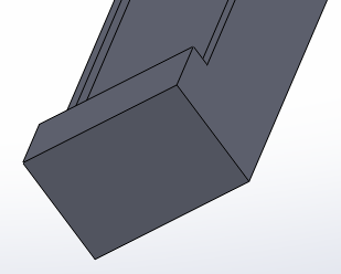
The result should look like this:

Add hole for inner rod
Now we have to cut a hole for the inner rod to lock into.

Make a sketch on the newly created “ledge” at the bottom of the actuator.

Draw a Point at the midpoint of the ledge.

Use this point as the center of a 12.7mm diameter circle.
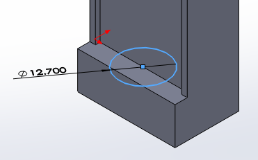

Using the same method as before (draw a diameter line and Trim), make this into a semicircle.
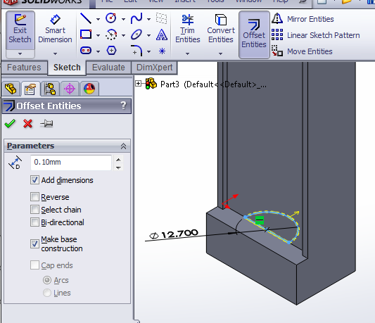
Next, we use Offset Entities to add 0.1mm for tolerance. This time we can offset everything, so use “Select chain.” Also check “Make base construction.”
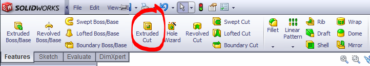
Using Extruded Cut, cut in both directions from the sketch plane: 6mm down and 2mm up.
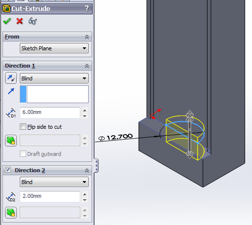
The result should look like this:

Align mold block and actuator
[Video: Make interim assembly for main mold]
Save the mold block part, then create a new assembly. This will be the interim assembly used for the Cavity feature.
In the assembly, add the mold block and actuator. Position them with 3 mates:
- Coincident: bottom face of actuator and bottom lip of mold
- Concentric: inner actuator cavity and rod hole in mold block
- Parallel: flat side of actuator, flat of mold block
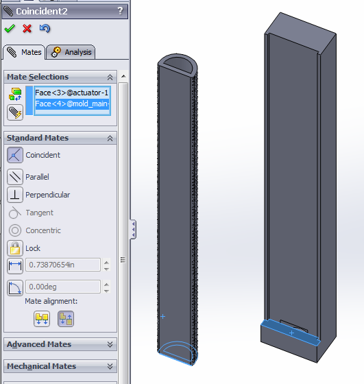
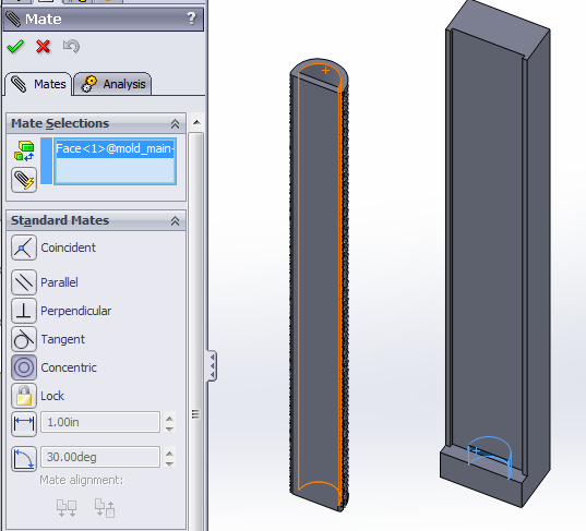
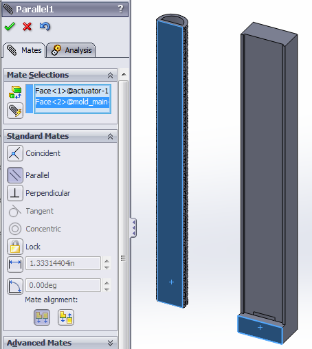
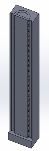
The final assembly should look like this:
Subtract actuator from mold block
[Video: Subtract actuator using the cavity feature to get main mold]
Now that the parts are properly positioned relative to each other, we can subtract the rod from the mold block with the Cavity feature.

Save the interim assembly (but don’t close it yet). Click on the mold block in the FeatureManager design tree, then click the “Edit Part” button in the menu that pops up.

Now you are editing the mold block within the assembly.
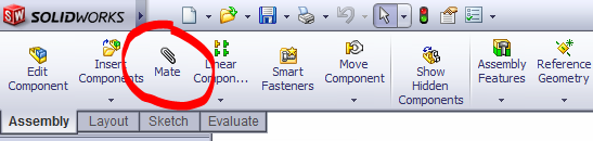
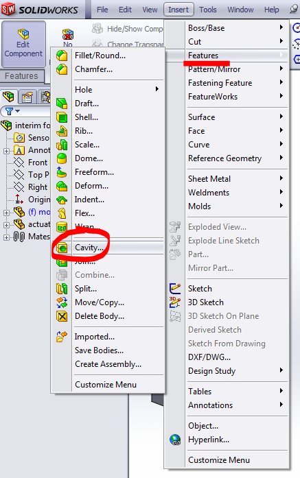
Now, use the Cavity feature (Insert > Features > Cavity). If it's not in the menu, go to Customize Menu and add it first.
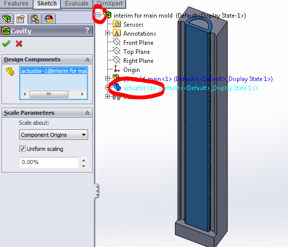
Select the Design Component, which is the part to subtract from the part you’re currently editing (the mold block). In this case, you want to subtract the actuator. To select it, expand the FeatureManager design tree and select the part corresponding the actuator.
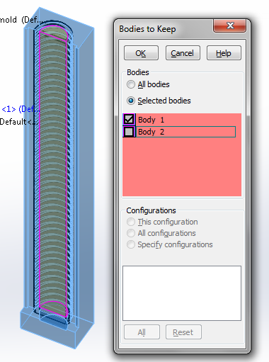
Click the check mark to complete the Cavity. A dialog will pop up asking about bodies to keep. This is because in addition to the mold block, there is another body created by the hollow space inside of the actuator. However, we don’t need this body for anything, so we select only the body corresponding to the mold block to keep.
Now that this mold piece is done, click the “Edit Component” button in the corner to return to the assembly.
Bibliography
Galloway et al. (2013) Mechanically programmable bend radius for fiber-reinforced soft actuators.
Maeder-York et al. (2014) Biologically Inspired Soft Robot for Thumb Rehabilitation.
Connolly et al. (2015) Mechanical Programming of Soft Actuators by Varying Fiber Angle
Connolly et al. (2016) Automatic Design of Fiber-Reinforced Soft Actuators for Trajectory Matching
Contributors
Panagiotis Polygerinos
Kevin Galloway
Zheng Wang
Fionnuala Connolly
Johannes T B Overvelde
Harrison Young