Make mold cap
The final part needed for the mold is the cap piece, which aligns the top of the inner rod during molding.
Get sketch for mold cap
To make the sketch for the cap, we can reuse the sketch from the actuator part file:

Open the actuator part file and expand the design tree so that you can see the sketch used to extrude the actuator body.
Select the sketch, then press CTRL+C to copy it.

Create a new part file, and press CTRL+V to paste the sketch.
Finalize sketch
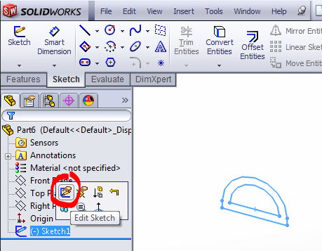
Edit the pasted sketch.
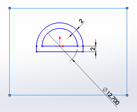
First, if it doesn’t show up already, smart dimension the 2mm wall thickness offsets to strictly define the sketch so we do not accidentally modify these values while making the following edits. Next, add a rectangle surrounding the sketch, which defines the edges of the mold cap.
The rectangle doesn't have to be perfectly centered and dimensioned for the mold cap to work -- just make sure that there is a comfortable margin around the lip.
However, if you want the cap to look nice and flush with the rest of the mold, then dimension the rectangle to 29mm x 19mm, distance the inner flat face of the actuator 6.5mm from the bottom, and use Add Relations to vertically align the center point of the rod arc with the midpoint of the bottom edge of the rectangle.

Extrude selected contours
As this sketch has multiple closed contours, when Extruding it we only extrude sections of it at a time using the “Selected Contours” options.
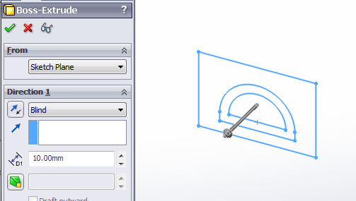

First, select the “D” shaped contour and extrude it 1.5mm.
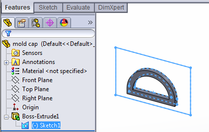
Select the sketch again in the design tree (it is now located under an extrude feature), then click Extrude in the Features toolbar to reuse it.
This time in "Selected Contours", select both the ‘D’ and the outer region of the sketch. Extrude it 3.5mm in the opposite direction from before (click the button with arrows next to “Blind” to reverse direction).

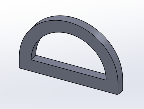
Complete the extrude. The final mold cap should look like this (front and back):
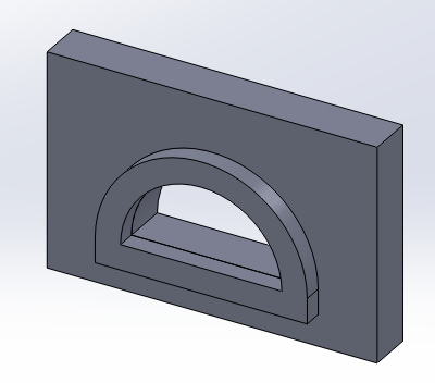
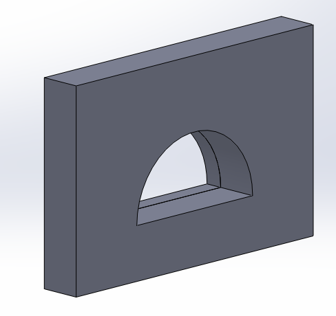
Fillet the outer corners of the lip, to match the fillet of the actuator (and corresponding cavity in the mold) so that the cap will fit. Alternatively, these corners can easily be cut or filed off after printing.

Bibliography
Galloway et al. (2013) Mechanically programmable bend radius for fiber-reinforced soft actuators.
Maeder-York et al. (2014) Biologically Inspired Soft Robot for Thumb Rehabilitation.
Connolly et al. (2015) Mechanical Programming of Soft Actuators by Varying Fiber Angle
Connolly et al. (2016) Automatic Design of Fiber-Reinforced Soft Actuators for Trajectory Matching
Contributors
Panagiotis Polygerinos
Kevin Galloway
Zheng Wang
Fionnuala Connolly
Johannes T B Overvelde
Harrison Young