Combine Chambers
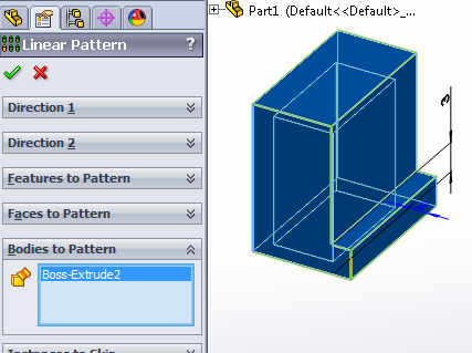
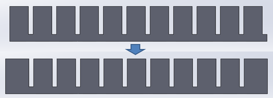
Now that we have the basic chamber, we will repeat it to create row of 11 chambers using the Linear Pattern feature. Since we need to pattern the entire chamber, we use Bodies to Pattern (instead of Features) and click on the chamber that we made. [Video: Patterning chambers in a row]
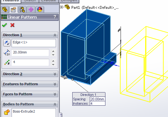
Now we select the direction to pattern the chamber. Under Direction 1, select an edge to determine the direction of patterning. You can use any edge parallel to the actuator main axis.
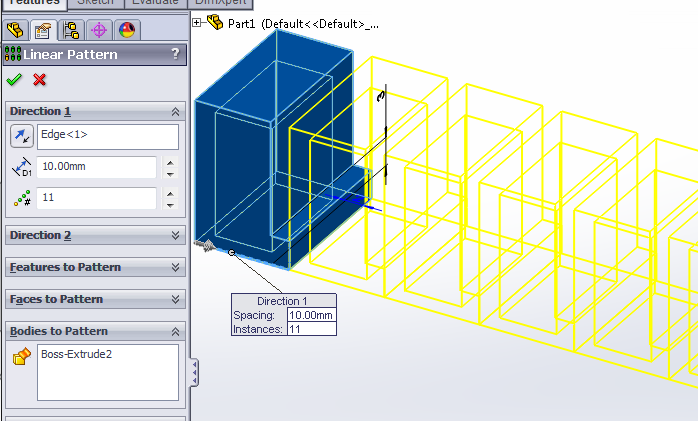
Set the distance to 10mm (8mm chamber thickness + 2mm spacer) and the pattern # to 11.
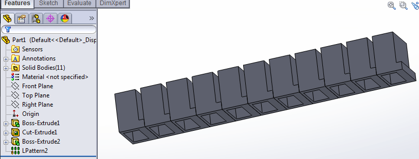
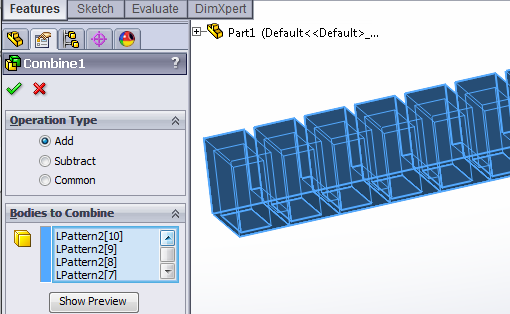
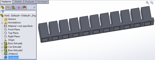
This gives us 11 separate solid bodies, which could be annoying later, so we merge them into a single solid body using the Combine feature.
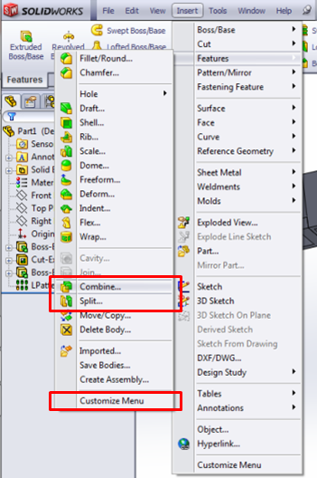
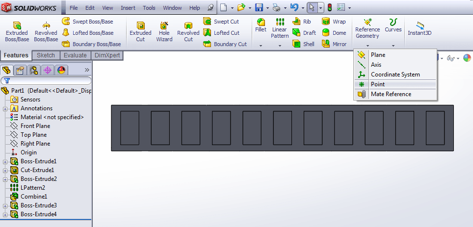
Combine is usually not available in the default toolbar. In the top dropdown menu, go to Insert > Features and click on Combine. If the option is not there, you will have to click on “Customize Menu” and manually add it – and add the Split feature as well, for later.
In Combine, use the Add operation type to add all the chamber bodies together. Under Bodies to Combine, select all the chambers.
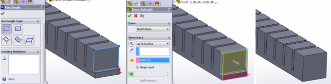
Next, we need to thicken the two ends of the actuator so that they don’t bulge out like the other sidewalls. To do this, use Extruded Boss/Base twice, to add 2mm extra thickness to each end wall. [Video: Thicken actuator ends]
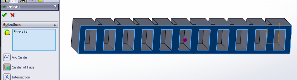
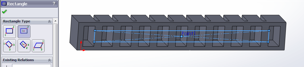
Now we cut the 2x2 mm central air channel. [Video: Cutting central air channel] To ensure that it is centered along the axis, we first need to create some reference geometry: a point that we can use to draw a centered rectangle later.
In the Point sidebar, select the “Center of Face” option, then click on the bottom face of the actuator (not inside a chamber). A dot should appear at the center.
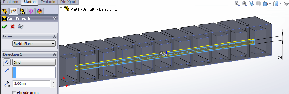
Now we use Extruded Cut to create the central channel. On the bottom face of the actuator, draw a rectangle using the reference point we just created as its center, and having its edge coincide with the inner face of one of the end chambers.
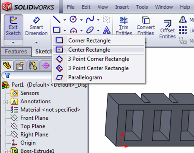
Use Smart Dimension to make the rectangle 2mm wide, then exit the sketch and make the Extruded Cut 2mm deep.
The main body of the actuator is now complete, but in the next step we will add some extra features to aid fabrication.
Bibliography
Ilievski et al. (2011) Soft robotics for chemists.
Mosadegh et al. (2013) Pneumatic Networks for Soft Robotics that Actuate Rapidly.
Ogura et al. (2009) Micro pneumatic curling actuator: Nematode actuator.
Polygerinos et al. (2013) Towards a soft pneumatic glove for hand rehabilitation.
Shepherd et al. (2011) Multigait soft robot.
Sun et al. (2013) Characterization of silicone rubber based soft pneumatic actuators.
Contributors
Panagiotis Polygerinos
Bobak Mosadegh
Alexandre Campo