Make Main Body Molds
Now that we have made a model of the main body we can use it to model the mold required to fabricate it.
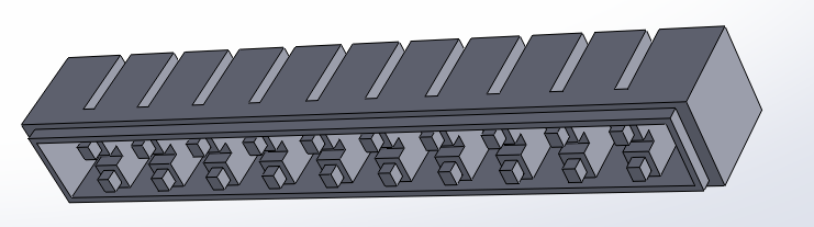
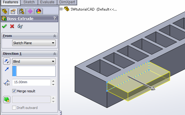
With Extrude, encase the actuator in a rectangular block, leaving about 4mm padding on every side, except for the top which should be flush with the top of the actuator. [Video: Encase actuator in mold block]
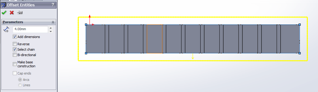
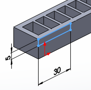
The simplest way to do this is to draw on the top side of the actuator. Make a construction rectangle that encompasses the entire face, then make a 4mm outwards offset using Offset Entities.
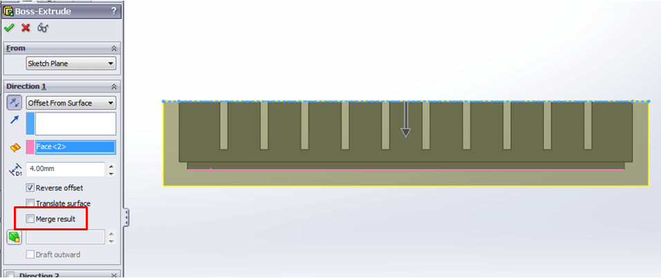
Extrude this large rectangle so that it encases the actuator, going 4mm past the bottom-most face of the actuator (the bonding ridge). You may have to reverse the direction and/or the offset. Make sure to uncheck the “Merge Result” option.
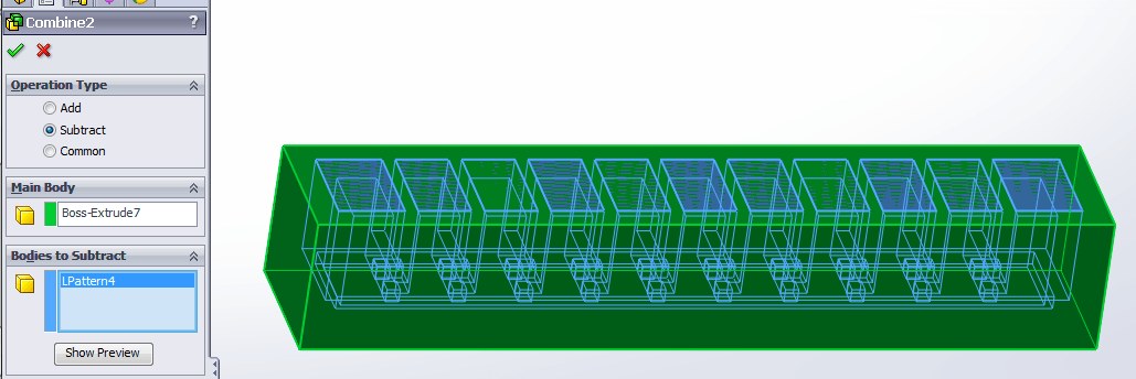
Next, we need to subtract the actuator body from the encasing block to get our mold. [Video: Subtract actuator from block] We do this by using the Combine feature again, but this time using the “Subtract” operation. Choose the encasing block as the “Main Body” and the actuator CAD model as the “Bodies to Subtract.”
We now have a mold; however, as it is, we cannot remove the molded piece without breaking the mold. We now have to divide the mold into 2 separate pieces which can be pulled apart for demolding. To do this, use the Split feature (Insert > Features > Split). [Video: Split mold]
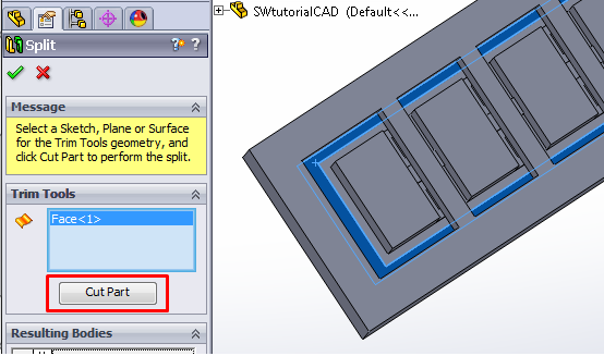
When using Split, the user must choose the plane along which the split occurs. Click the box under Trim Tools so that it is highlighted, then select the face for splitting.
The face we want is the one that corresponds to the bottom of the actuator, excluding the bonding ridge/bumps. Look at the mold from the top, where the holes are, and select the rectangular face closest to the outer wall of the mold. (The inner one is the depression corresponding to the bonding ridge on the bottom of the actuator.)
Once the face is selected, click the “Cut Part” button.
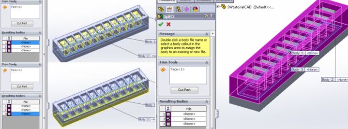
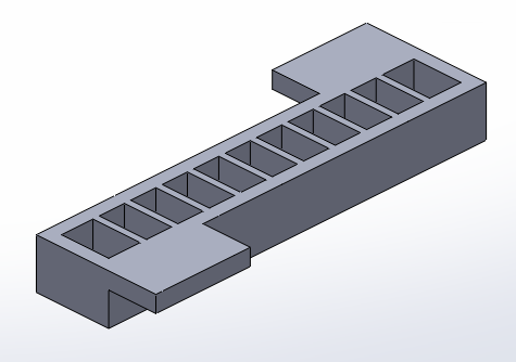
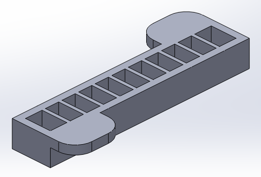
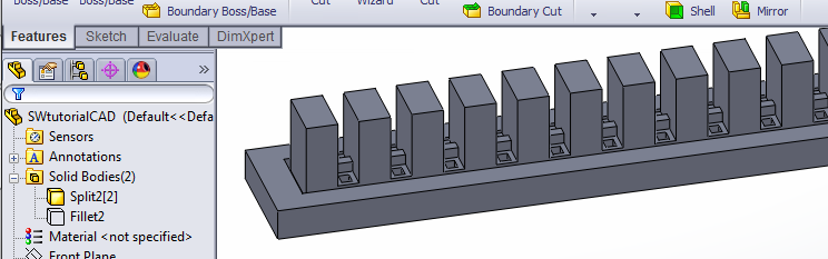
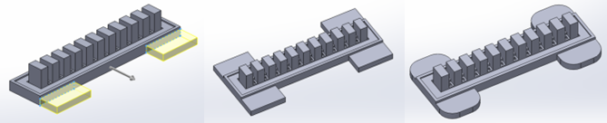
The cut will result in 3 bodies. Select the one that looks like a ladder (as in the last image) and check its box, then finalize the Split by clicking the green check mark.
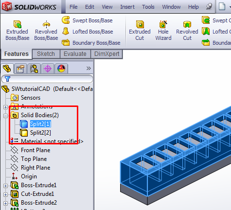
There should now be two solid bodies in this document, one corresponding to the top mold piece and one for the bottom. You should be able to see them near the top of the FeatureManager Design Tree on the side of the window.
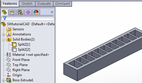
We will edit each of these bodies to add features that make the molding process easier. First, hide the bottom body so that it doesn’t clutter the view while we edit the top part. Click on the bottom body and a small menu will appear. Click on the glasses icon to hide the body.
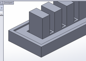
Now, only the top mold piece should be visible:
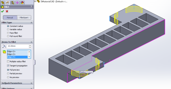
To this piece, we will add tabs on the side to provide grip when pulling the mold pieces apart. [Video: Edit top mold piece] Use Extrude and draw a rectangle in the top corner of one of the side faces. Extrude it out to create a tab. Repeat for the other side.
You can round out the grip tab corners so it looks nicer (though it is not necessary) by using the Fillet tool, and selecting the 4 sharp edges of the tabs.
This piece is now complete and ready for printing. Save it as an .STL file (or whatever file format your 3D printer uses): File > Save As and set “Save as type” to STL (*.stl)
Now we need to edit the other half of the mold. Hide the current body, and unhide/show the other one (using the glasses icons again). [Video: Edit bottom mold piece]
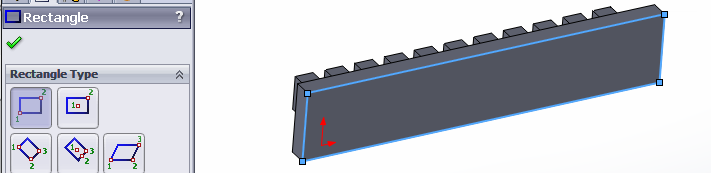
To this part we will add a raised lip around the perimeter to help align the two mold pieces.
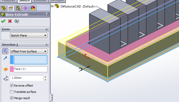
An easy way to do this is to Extrude an offset from the flat bottom face of the part. Draw a rectangle that encompasses the entire bottom face, then while it’s still highlighted, use Offset Entities to create a small outwards offset.
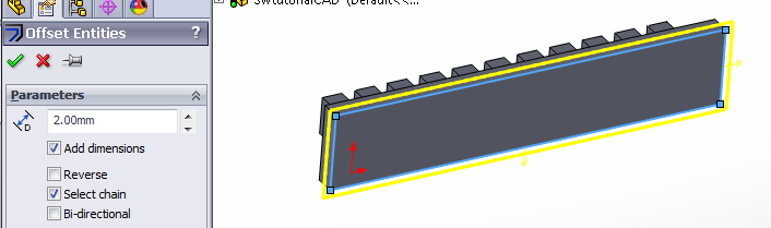
Once this sketch is complete, extrude it upwards, towards the top of the mold piece, so that it’s raised slightly above the mold floor, creating a lip. You may have to reverse the direction, or if you use “Offset from Surface” you may have to reverse the offset.
Now that the alignment lip is complete, create tabs for this piece as well, using the same method as before. Once the piece is complete, save it as another .STL file.
The molds for the main body are now complete. In the next step, we will make the mold for the base layer
Bibliography
Ilievski et al. (2011) Soft robotics for chemists.
Mosadegh et al. (2013) Pneumatic Networks for Soft Robotics that Actuate Rapidly.
Ogura et al. (2009) Micro pneumatic curling actuator: Nematode actuator.
Polygerinos et al. (2013) Towards a soft pneumatic glove for hand rehabilitation.
Shepherd et al. (2011) Multigait soft robot.
Sun et al. (2013) Characterization of silicone rubber based soft pneumatic actuators.
Contributors
Panagiotis Polygerinos
Bobak Mosadegh
Alexandre Campo