Honeycomb Structure
Design parameter
For the same material, different structures can make vast difference on mechanical properties.
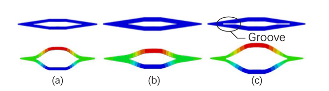
Specifically, for a single honeycomb chamber, the figure above illustrates the difference of deformation about different wall thickness and with the addition of grooves under the same pressure and cross section area. The structure with a thicker wall appears are more stable however the addition of the inner grooves imparts additional flexibility to the structure.
Thus, we use flexibility and load bearing capacity as the evaluation metrics of mechanical property of the HPN manipulator. Flexibility is defined as the ratio of the reachable area of the manipulator's tip to the square of manipulator's original length. And load bearing capacity is defined as the maximum load moment under the condition that the manipulator's tip can hold stably at the same height with its fixed end. The definitions have relations with the original length of the manipulator, however, the connection can be approximately omitted.
Later, we will illustrate the model design procedure and use FEM simulations to estimate the relationship between flexibility, load bearing capacity and wall thickness, as well as groove depth. The result can be viewed on the testing page.
Honeycomb structure

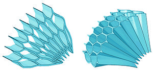
The honeycomb structure we use to make manipulators consists of compressed hexagonal chambers. This structure has many advantages, such as a high elongation rate and crush resistance, When airbags inside pressurize, some of the chambers deform, so the structure elongates or bends.
Before making our model we must determine the design parameters. There are several dimensions that affect the actuator’s behavior: wall thickness, and groove depth.

Model design CAD tutorial
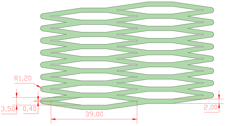
This tutorial contains step-by-step instructions for making a solid model of a Honeycomb structure in SolidWorks 2015. The SolidWorks part files can be downloaded here. If you prefer to use a different software package, you should be able to apply the general tutorial steps to most solid modeling environments or you can refer to the dimensioned figures below.
In addition, there are other design parameters to be determined: chamber height, and overall number of chambers.
In this tutorial we will make an honeycomb structure with 2 columns, each column have 8 chambers. Each chamber is 3.5 mm long, 39 mm wide, 60 mm high, with 2 mm wall thickness. Of course, you can alter these parameters to change the morphology of your actuator yet general steps covered in the tutorial should still apply.
Bibliography
Jiang et al. (2016) Design and Simulation Analysis of a Soft Elastomer Manipulator based on Honeycomb Pneumatic Networks.
Sun et al. (2016) FLEXIBLE HONEYCOMB PNEUNETS ROBOTS.
Jiang et al. (2017) A Two-Level Approach for Solving the Inverse Kinematics of an Extensible Soft Arm Considering Viscoelastic Behavior.
Jiang et al. (2016) Design and Simulation Analysis of a Soft Manipulator Based on Honeycomb Pneumatic Networks.
Giri et al. (2010) Continuum robots and underactuated grasping
Grissom, et al. (2006) Design and experimental testing of the OctArm soft robot manipulator.
Contributors
Hao Jiang
Zhanchi Wang
Xinghua Liu
Xiaotong Chen
Yusong Jin
Hao Sun
Xiaoping Chen